
ArtInChip D126 Wi-Fi / BLE
This guide combines ArtInChip (匠芯创) D126FxR-DEMO-V1-1 board documentation with project-provided wireless bring-up notes. The core sequence initializes AIC8800DW and its Bluetooth patch over SDIO, then starts the NimBLE BLE example over UART3 HCI.
Scope
Board specifications come from ArtInChip. The internal AIC8800DW connections, pin multiplexing, patch selection and example logs come from project notes without an SDK commit ID. Check them against your actual Luban-Lite tree; they are not guaranteed to apply to every D126 package or SDK release. No physical-board testing was performed for this article.
Product specifications
| Item | Official reference-board configuration |
|---|---|
| Board | D126FxR-DEMO-V1-1 |
| Package | BGA124 |
| Memory / storage | 8/16 MB PSRAM; 16 MB SPI NOR |
| Display / touch | MIPI + CTP |
| Communications | RS485, CAN, UART |
| Wireless / expansion | SDIO WiFi, TF-Card |
| Multimedia | Camera, Audio |
These are board configurations, not universal specifications for all D126 ordering codes. The cited page does not establish Wi-Fi standards, frequency bands, BLE version or RF performance. Source: ArtInChip D126 board documentation.
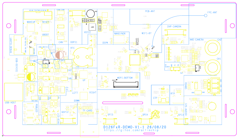
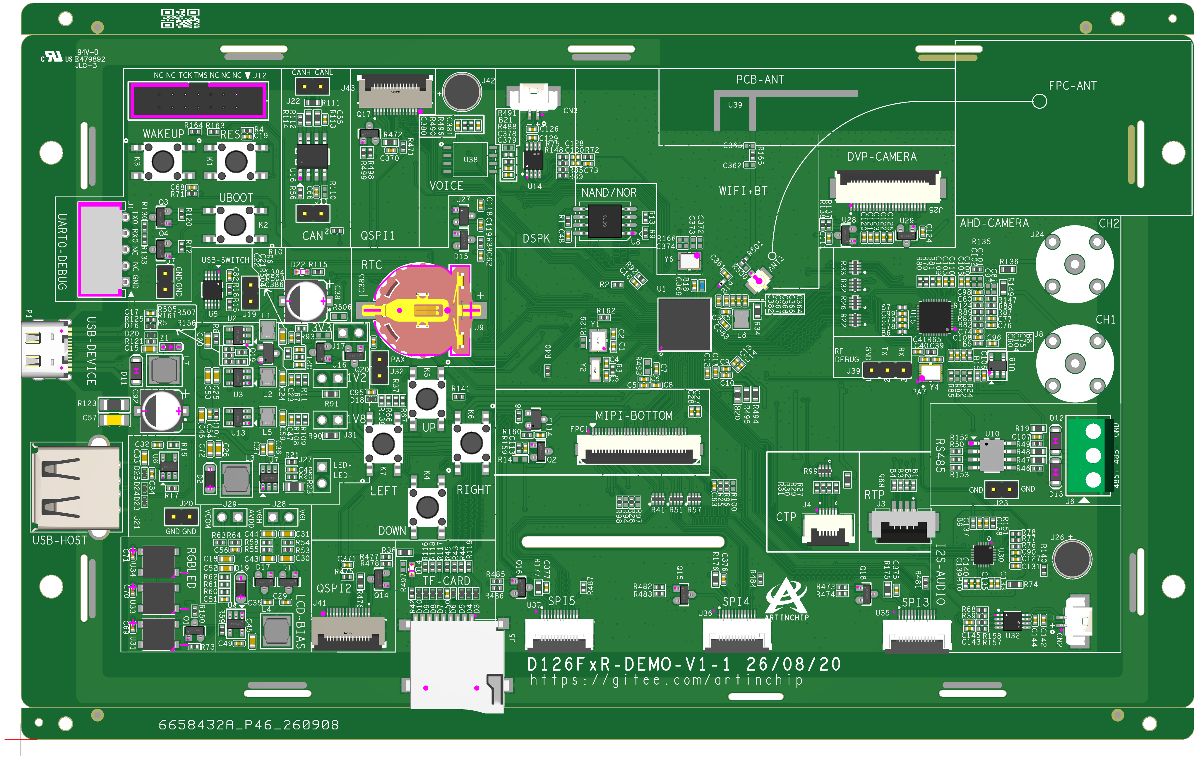
Images: ArtInChip board documentation; copyright remains with the respective rights holder. Consult the official schematic for hardware design.
Hardware connections
The updated project notes hypothesize that the D126 package contains two dies: a D12P SoC and an AIC8800DW radio. This is a project hypothesis, not a package configuration confirmed by manufacturer documentation. The CPU runs Luban-Lite and NimBLE. The identifiers below are SoC signals, not development-board header numbers; do not use them as jumper wiring instructions.
| Connection | Pins / mux function | Purpose |
|---|---|---|
| SDMC1 / SDIO | PE.12–PE.17, function 8 | Wi-Fi firmware and Bluetooth patch download; Wi-Fi data |
| UART3 TX | PB.18, function 7 | CPU → Bluetooth controller |
| UART3 RX | PB.19, function 7 | Bluetooth controller → CPU |
| UART3 flow control | PB.20, PB.21, function 7 | RTS/CTS; verify individual assignments in the actual pinmux |
| Wi-Fi power control | PE.18, function 1 | GPIO enable |
| Bluetooth power control | PE.20, function 1 | GPIO enable |
| Wake control | PA.6, function 1 | GPIO wake |
The notes describe these three GPIO controls as active high. Let the driver manage them and verify board-specific levels and sequencing rather than adding arbitrary manual GPIO operations.
BLE HCI uses UART3, 1500000 baud, 8N1, H4 and RTS/CTS hardware flow control. Host settings must match the downloaded controller patch.
D126 CPU
  +-- SDMC1 / SDIO --> AIC8800DW: Wi-Fi firmware, Bluetooth patches, Wi-Fi data
  +-- UART3 / H4  <--> Bluetooth controller: NimBLE HCI
  +-- GPIO         --> Power enables and wake control
Software Quickstart
1. Select the board project
The official board page lists the following identifiers. Select them in the matching SDK; the configuration name is not itself a shell command.
| Item | Path / identifier |
|---|---|
| Project directory | target/d12p/d126-demo124-nor/ |
| Default configuration | d12p_d126-demo124-nor_rt-thread_helloworld_defconfig |
| Firmware path | output/d12p_d126-demo124-nor_rt-thread_helloworld/images/d12p_d126-demo124-nor_v1.0.0.img |
This is a starting configuration, not evidence that NimBLE or ble_hr is already enabled. Follow your SDK's build and flashing instructions, establish a working console, then apply the configuration below.
2. Configure pinmux and the Wi-Fi driver
- Select function 8 for PE.12–PE.17 and configure SDMC1 for SDIO.
- Select function 7 for PB.18–PB.21 to route UART3.
- Select function 1 for PE.18, PE.20 and PA.6 for driver-managed GPIO controls.
- Select AIC8800DW and configure its power and wake pins.
- Enable
enable BT supportso wireless initialization also downloads the Bluetooth patch.
Menu locations, symbols and source paths can differ between SDK releases. Do not blindly copy another chip's board configuration.
3. Check the Bluetooth patch branch
The project notes route DW through the same DC-H branch as DC in aicbt_patch_trap_data_load(), not the D80 branch. For the recorded chip_sub_id=2, the patch identifiers are:
fw_adid_8800dc_u02hfw_patch_8800dc_u02h
This is revision-specific information. Do not force every device's chip_sub_id to 2. Check the detected silicon revision and SDK patch-selection logic first. A mismatched patch can interrupt download or leave the controller unresponsive.
4. Configure NimBLE HCI
Point NimBLE HCI to uart3, select H4 and verify 1500000 baud, 8N1 and RTS/CTS. Enable the heart-rate example that provides ble_hr.
The notes distinguish D126's UART3 from UART2 in a separate D133 external-module example. Do not copy that UART2 configuration into this setup.
5. Initialize wireless before starting BLE
Run on the board console:
wifi -d mode sta wlan0Wait for firmware and patch loading to finish. The recorded success message is:
wifi open okThen run:
ble_hrExpected example log:
GAP procedure initiated: advertiseUse a phone BLE scanner to look for blehr_sensor. This is the name recorded in the notes and may differ in customized firmware. Seeing advertisements does not validate every GATT operation.
Initialization is not a network connection
In this example, wifi -d mode sta wlan0 initializes STA mode. Router association, credentials, IP acquisition and network traffic testing require the commands documented by your SDK; this guide does not imply that the initialization command performs them.
Frequently asked questions
Do D126 Wi-Fi and BLE share a UART?
According to the project notes, Wi-Fi traffic, firmware and Bluetooth patch downloads use SDMC1 / SDIO. NimBLE Bluetooth HCI uses UART3. These paths have different roles.
Why initialize Wi-Fi before running ble_hr?
This example loads the Bluetooth patch through wireless initialization. Wait for wifi open ok before starting ble_hr so the controller is ready.
What BLE name should a phone find?
The recorded heart-rate example advertises as blehr_sensor. Advertising does not establish Wi-Fi connectivity or validate all GATT operations.
Is the D126 two-die package confirmed?
No. It remains a project hypothesis, not a manufacturer-confirmed package specification.
Related guide: ArtInChip D125 board-verified cJTAG debugging.
Troubleshooting
| Symptom | Check first |
|---|---|
| wifi or ble_hr command missing | Driver, console command components and heart-rate example |
| No wifi open ok | SDMC1 / SDIO pinmux, power GPIOs, AIC8800DW selection and download logs |
| Patch download stops or controller does not respond | Silicon revision, DC-H versus D80 branch and patch files |
| Wi-Fi initializes but BLE does not respond | BT support, UART3, 1500000 baud, H4 and RTS/CTS |
| Advertising log appears but phone finds nothing | Advertising name, scan permissions, distance, antenna and RF hardware |
| BLE advertises but Wi-Fi is offline | Test each subsystem separately; BLE advertising does not establish Wi-Fi association or an IP address |
Keep the complete boot log, SDK revision, configuration changes and detected silicon revision rather than diagnosing from the last error alone.
Sources and validation limits
- ArtInChip D126 board documentation: board specifications, project identifiers and both images.
- D126FxR-DEMO-V1-1 schematic: hardware reference.
- Project-provided D126 wireless notes: SDIO / UART3 / GPIO mappings, patch selection, commands and logs. An SDK commit ID and reproducible physical-board test record are still needed.