
X2MIPI / X2CSI Hardware and Driver Porting
X2MIPI (also X2CSI) bridges USB-C, HD, or DP video sources to MIPI CSI-2 so they can feed CSI receivers on Raspberry Pi, NVIDIA Jetson, Rockchip, and other SoCs. This page covers hardware notes, driver integration, and platform porting.
Resources, Hardware, and Support
Design resources, hardware PCBA purchase, and technical support are available through doc.ultrasemi.com.
1. Hardware Introduction
X2MIPI hardware supports several video-input to MIPI CSI-2 bridge applications:
- USB-C to MIPI CSI
- HD to MIPI CSI
- DP to MIPI CSI
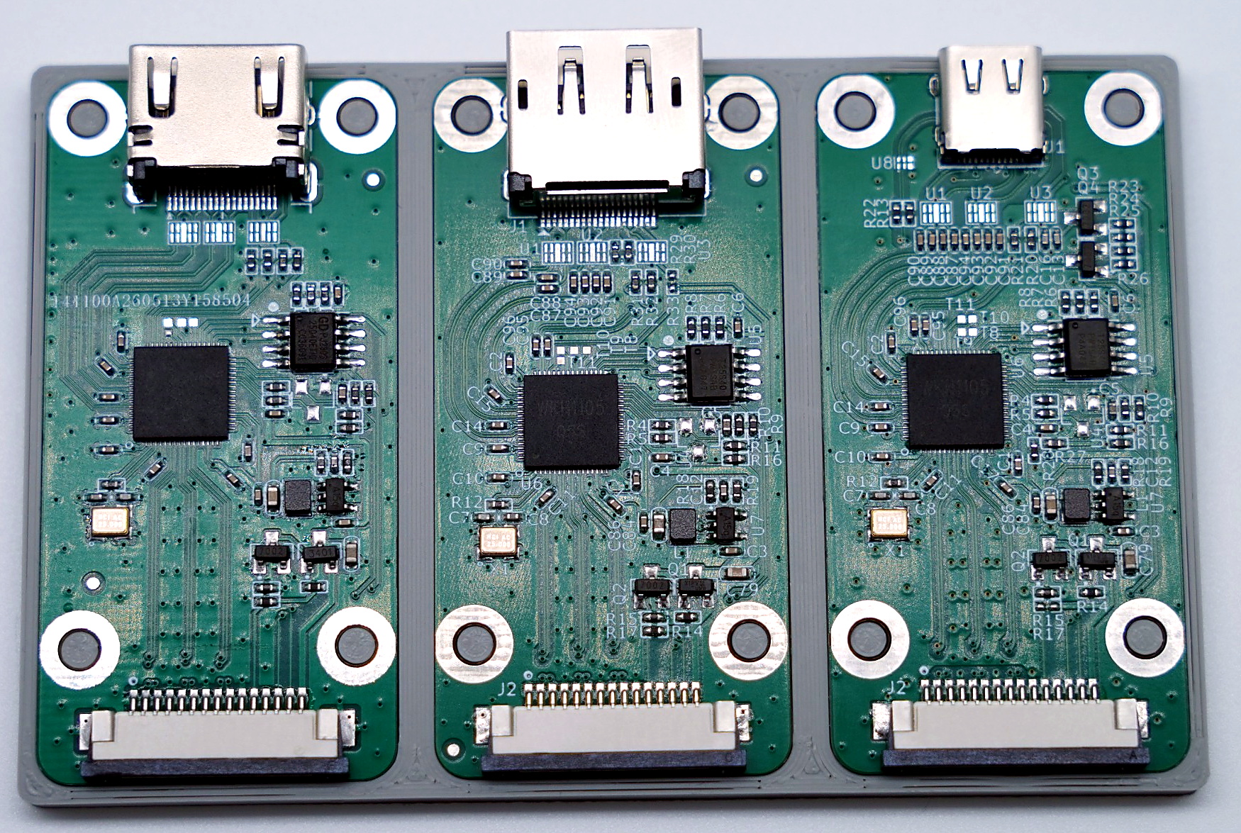
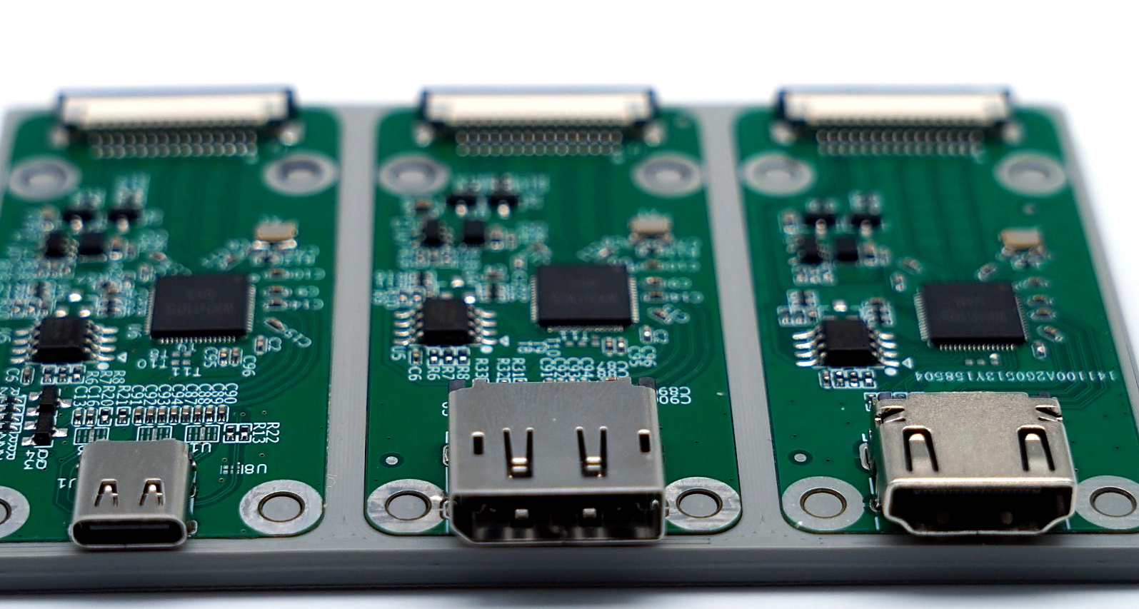
During hardware design and platform adaptation, confirm:
- CSI lane count: commonly 2-lane or 4-lane; the SoC device tree must match the hardware.
- I2C control: the driver talks to the bridge over I2C; the example address is
0x58. - Device-tree compatible:
compatible = "ultrasemi,lk-x2mipi". - Input source and EDID: write EDID through a character device and read back input status / resolution.
- Clock, power, and reset: add platform-specific resources for the real board.
2. Driver Porting
The driver is a Linux I2C V4L2 subdev driver. Key functions include:
- Video input timing detection and V4L2 DV timings query.
- MIPI CSI-2 output configuration from endpoint
data-lanesor overlay parameters. - V4L2 subdev events for source-change cases.
- EDID update and input-status readback through
/dev/lk_x2mipi.
2.1 Raspberry Pi Porting
2.1.1 Raspberry Pi 3
Use a 15-pin 0.1" reverse FFC to the Raspberry Pi 3 CAMERA connector.
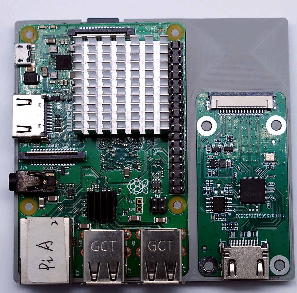
Prefer kernel 6.12 or newer.
Clone the full lk_x2mipi tree onto the Pi, for example /home/lk_x2mipi/RaspberryPi3. The package is meant to build on-device. Typical layout:
lk_x2mipi/
├─ module/
│  ├─ Makefile
│  └─ lk_x2mipi.c
├─ overlay/
│  └─ lk_x2mipi-overlay.dts
└─ scripts/
   ├─ build.sh
   └─ install.sh
Install build dependencies:
sudo apt update
sudo apt install -y bc bison flex libssl-dev make device-tree-compiler raspberrypi-kernel-headers
ls -l /lib/modules/$(uname -r)/build
Build and install:
cd lk_x2mipi/RaspberryPi3
chmod +x scripts/*.sh
./scripts/build.sh
sudo ./scripts/install.sh
Outputs are module/lk_x2mipi.ko and overlay/lk_x2mipi.dtbo. The install script places the module under /lib/modules/$(uname -r)/extra/, runs depmod -a, and installs the overlay to /boot/overlays/ or /boot/firmware/overlays/.
Enable the overlay:
sudo nano /boot/firmware/config.txtIn /boot/firmware/config.txt (or /boot/config.txt on some images):
camera_auto_detect=0
dtoverlay=lk_x2mipi
Default overlay is 2-lane CSI. On CAM0:
dtoverlay=lk_x2mipi,cam0When the hardware uses four CSI data lanes:
dtoverlay=lk_x2mipi,4laneMedia-controller mode when required:
dtoverlay=lk_x2mipi,media-controller=1After reboot, run the common checks below. If /dev/video0 is missing, confirm the system loads /boot/firmware/overlays/lk_x2mipi.dtbo, then rebuild and reinstall to replace any older overlay.
Common validation commands:
dmesg | grep -i lk_x2mipi
v4l2-ctl --list-devices
media-ctl -p
Write EDID to the bridge:
sudo dd if=/path/to/edid.bin of=/dev/lk_x2mipi bs=512 count=1
dmesg | grep -i "EDID updated"
Read resolution, frame rate, audio sample rate, and input-lock status:
sudo dd if=/dev/lk_x2mipi bs=24 count=1 2>/dev/null | hexdump -CWhen the read buffer is at least 24 bytes, the driver returns six int fields:
| Index | Field | Meaning |
|---|---|---|
| 0 | w | Detected width in pixels |
| 1 | h | Detected height in pixels |
| 2 | fps | Estimated frame rate |
| 3 | audio_sample | Audio sample rate in Hz; 0 when unavailable or unknown |
| 4 | change | Whether input-lock status changed since the previous read; 1 means changed |
| 5 | rx_insert | Current input lock or insertion status; 1 means signal present |
2.1.2 Raspberry Pi 5
Use a 15-pin 0.1" to 22-pin 0.05" same-direction FFC to the Raspberry Pi 5 CAM/DISP connector.
Notes:
- Verified on:
Linux raspberrypi 6.18.39+rpt-rpi-2712 #1 SMP PREEMPT Debian 1:6.18.39-1+rpt1 (2026-07-29) aarch64 GNU/Linux - Prefer kernel 6.12 or newer
- Use the on-board CAM/DISP connector
- RP1-CFE must match the MIPI link frequency; the current example uses 297 MHz (
1920×1080P@30). To change the rate, update bothlink-frequenciesinoverlay/lk_x2mipi-overlay.dtsandLK_X2MIPI_LINK_FREQinlk_x2mipi.c - Mainline marks
UYVY_2X8as an invalid CSI-2 format (it is not transferred as two bytes). Replace RP1-CFE with a build that supportsUYVY_2X8before use
Clone the full lk_x2mipi tree, for example /home/lk_x2mipi/RaspberryPi5. Typical layout:
raspberrypi5/
│
├─ rp1-cfe-downstream.ko    # replacement driver
│
├─ module/
│  ├─ Makefile
│  └─ lk_x2mipi.c           # module source (builds lk_x2mipi.ko)
├─ overlay/
│  └─ lk_x2mipi-overlay.dts
└─ scripts/
   ├─ build.sh
   └─ install.sh
Install build dependencies:
sudo apt update
sudo apt install -y bc bison flex libssl-dev make device-tree-compiler raspberrypi-kernel-headers
ls -l /lib/modules/$(uname -r)/build
Replace the RP1-CFE driver. The following removes the stock module and installs rp1-cfe-downstream.ko from the raspberrypi5 folder:
sudo rm /lib/modules/$(uname -r)/kernel/drivers/media/platform/raspberrypi/rp1_cfe/rp1-cfe-downstream.ko.xz
sudo cp /home/lk_x2mipi/raspberrypi/raspberrypi5/rp1-cfe-downstream.ko /lib/modules/$(uname -r)/kernel/drivers/media/platform/raspberrypi/rp1_cfe/
Refresh module dependencies:
sudo depmod -aBuild and install:
cd lk_x2mipi/RaspberryPi5
chmod +x scripts/*.sh
./scripts/build.sh
sudo ./scripts/install.sh
Outputs are module/lk_x2mipi.ko and overlay/lk_x2mipi.dtbo. The install script places the module under /lib/modules/$(uname -r)/extra/, runs depmod -a, and installs the overlay to /boot/overlays/ or /boot/firmware/overlays/.
Enable the overlay:
sudo nano /boot/firmware/config.txtIn /boot/firmware/config.txt (or /boot/config.txt):
camera_auto_detect=0
dtoverlay=lk_x2mipi
Default overlay is 2-lane CSI. On CAM0:
dtoverlay=lk_x2mipi,cam0Four CSI data lanes when required by hardware:
dtoverlay=lk_x2mipi,4laneValidate after reboot:
dmesg | grep -i lk_x2mipi
media-ctl -p
v4l2-ctl --list-devices
You should see media pipeline output with rp1-cfe and /dev/video0. If /dev/video0 is missing and rp1-cfe is absent from the list, re-check the overlay and RP1-CFE replacement.
dtoverlay=lk_x2mipi loads only /boot/firmware/overlays/lk_x2mipi.dtbo. If an older file is present, rerun ./scripts/build.sh and sudo ./scripts/install.sh to overwrite it.
Default MIPI configuration at probe
After a successful probe the driver programs MIPI once. Lane count comes from the active overlay endpoint:
- Default
dtoverlay=lk_x2mipi→ 2-lane dtoverlay=lk_x2mipi,4lane→ 4-lane
Update EDID via character device
The driver creates:
/dev/lk_x2mipi
Write an EDID blob (up to 512 bytes) to push it to the bridge, for example:
sudo dd if=/path/to/edid.bin of=/dev/lk_x2mipi bs=512 count=1Check the update result:
dmesg | grep -i "EDID updated"Read current resolution and status (read)
A read(2) of at least 24 bytes on /dev/lk_x2mipi returns six little-endian int values in the legacy struct gsv_info layout (same endianness as the process):
| Index | Meaning |
|---|---|
| 0 | Width w (pixels) |
| 1 | Height h |
| 2 | Frame rate fps (from pixel clock and total rows/columns, rounded) |
| 3 | Audio sample rate audio_sample (Hz; 0 if none/unknown) |
| 4 | change: whether input-lock status changed since the previous read (1 = changed) |
| 5 | rx_insert: input lock / insert status (1 = signal present) |
Without valid timings (for example no source), read still succeeds but early fields may be 0.
Example (read 24 bytes and dump raw content):
sudo dd if=/dev/lk_x2mipi bs=24 count=1 2>/dev/null | hexdump -CConfigure the media pipeline
Set DV timings (often subdev2; use the real index if different):
v4l2-ctl -d /dev/v4l-subdev2 --set-dv-bt-timings queryFind the media device:
M=$(for d in /dev/media*; do
  media-ctl -d $d -p 2>/dev/null | grep -q lk_x2mipi && echo $d && break
done)
echo MEDIA=$M
This prints the media device in use.
Reset the pipeline:
sudo media-ctl -d $M -rDisconnect the link to pisp-fe:
sudo media-ctl -d $M -l "'csi2':4 -> 'pisp-fe':0 [0]"Enable csi2 -> video0:
sudo media-ctl -d $M -l "'csi2':4 -> 'rp1-cfe-csi2_ch0':0 [1]"Set csi2 sink and source pad formats:
sudo media-ctl -d $M -V "'csi2':0 [fmt:UYVY8_2X8/1920x1080 field:none colorspace:smpte170m]"
sudo media-ctl -d $M -V "'csi2':4 [fmt:UYVY8_2X8/1920x1080 field:none colorspace:smpte170m]"
Capture an image. Try grabbing one frame with:
v4l2-ctl -d /dev/video0 --set-fmt-video=width=1920,height=1080,pixelformat=UYVY --stream-mmap=3 --stream-count=1 --stream-to=image_uyvy.yuvInspect the file:
ls -l image_uyvy.yuvAt 1920×1080, the file size should be 4147200 bytes.
2.2 Jetson Porting
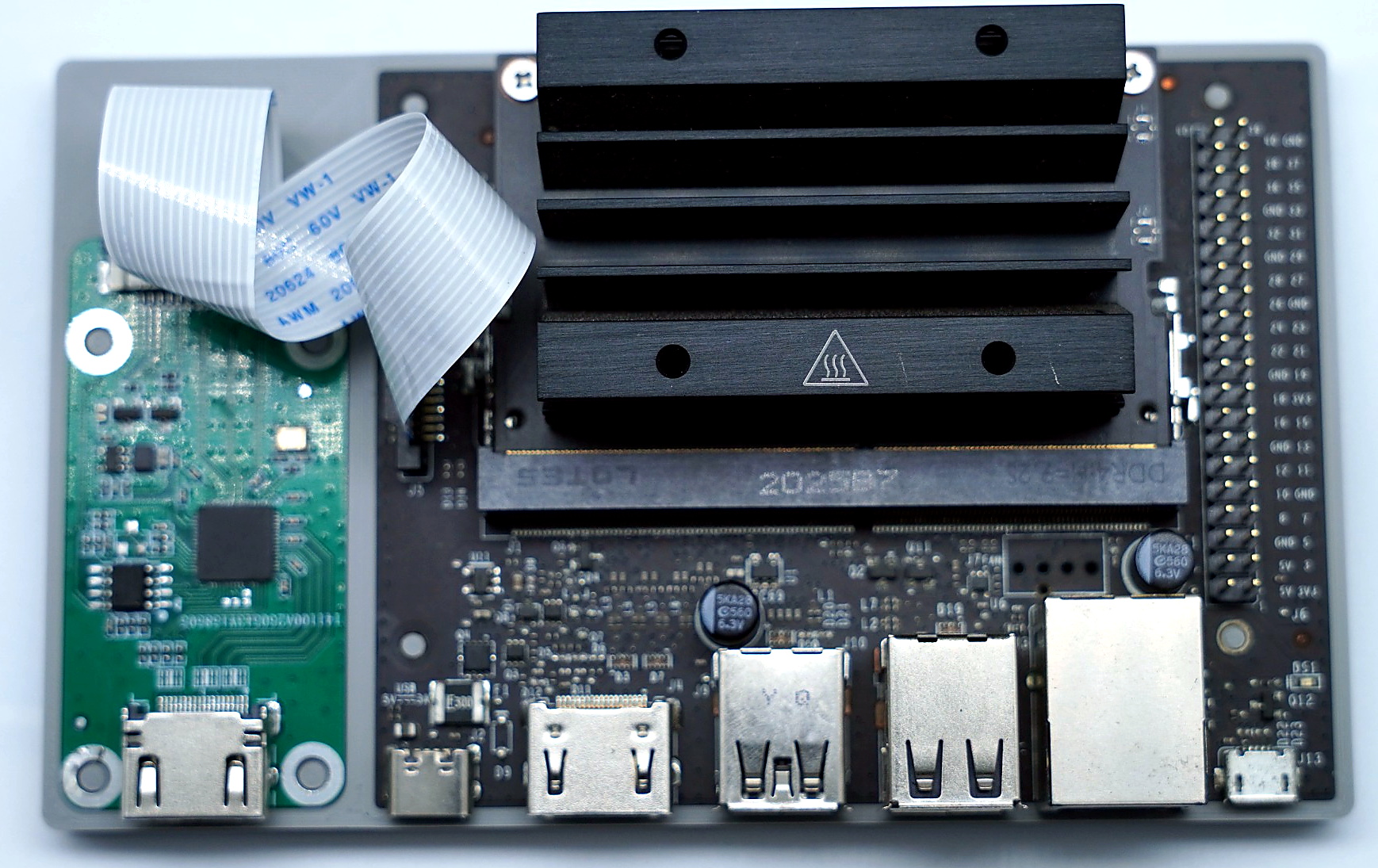
On Jetson/L4T, integrate the driver into the target kernel tree with a Kconfig + Makefile + C layout:
jetson/
├─ Kconfig
├─ Makefile
└─ lk_x2mipi.c
Kernel integration steps:
- Place the driver directory under a suitable path in the Jetson kernel tree.
- Add a
sourceentry in the parentKconfig. - Add a subdirectory build entry in the parent
Makefile, for exampleobj-y += lk_x2mipi/jetson/. - Enable
CONFIG_VIDEO_LK_X2MIPI_JETSON=yorCONFIG_VIDEO_LK_X2MIPI_JETSON=m.
The device tree should describe:
- An I2C node with
compatible = "ultrasemi,lk-x2mipi". - Address
reg = <0x58>. - Endpoint links to the CSI receiver and matching
remote-endpoint. data-lanesfor 2-lane or 4-lane MIPI.- Platform clock, power, and reset resources.
On some Jetson platforms, loading the module alone may not finish VI async bridge registration, so /dev/video0 never appears. After camera/VI adaptation, enable the VI bridge explicitly:
sudo /sbin/insmod ./lk_x2mipi.ko vi_bridge=1Validate against the target L4T release and camera_common integration before relying on this long term.
2.3 RK Porting
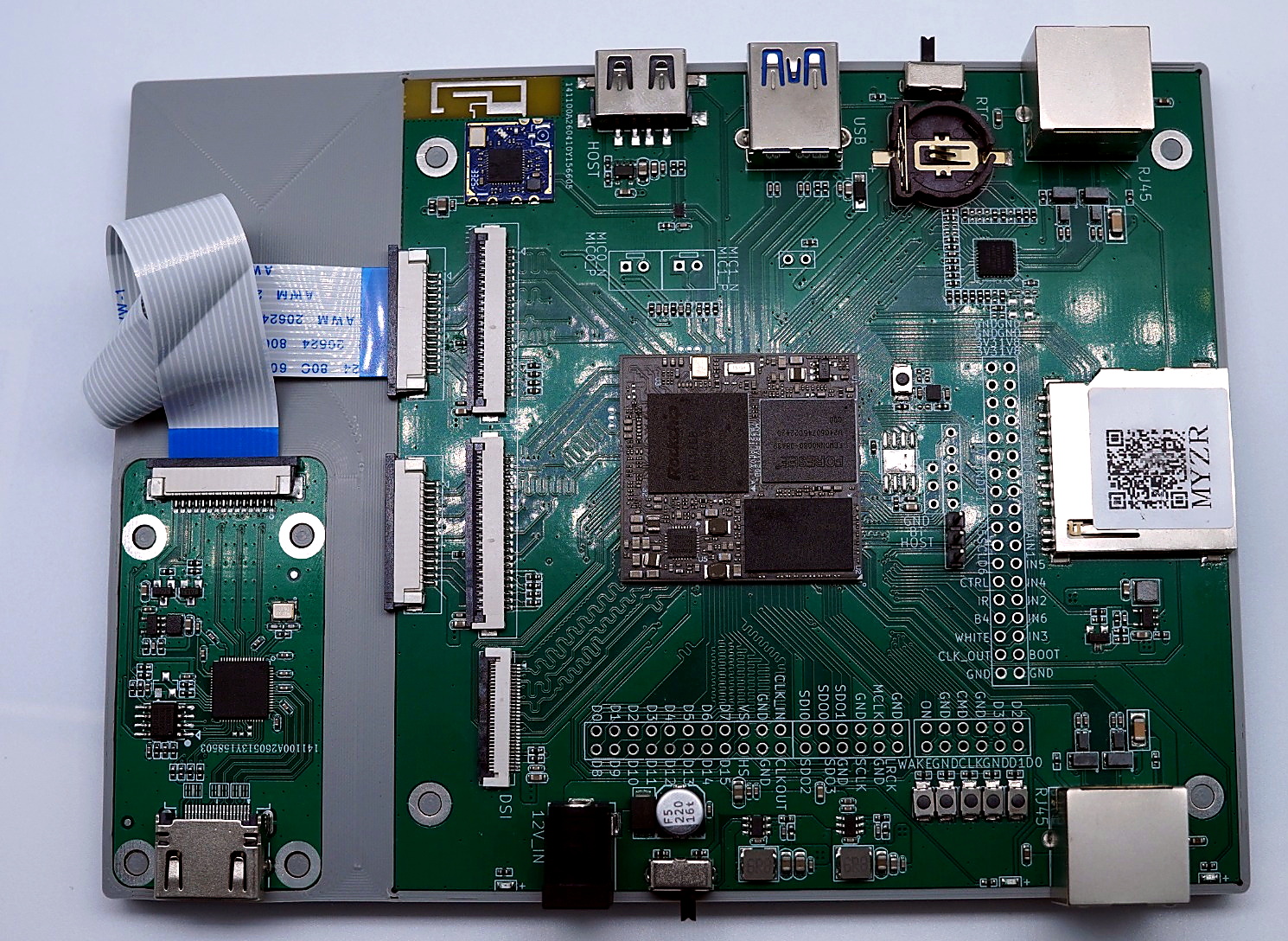
Rockchip platforms can use the generic Linux kernel driver flow (for example RV1126B and other SoCs with a MIPI CSI receiver):
linux/
├─ Kconfig
├─ Makefile
└─ lk_x2mipi.c
Kernel integration steps:
- Place the driver under the target kernel media/video tree.
- Add a
sourceentry in the parentKconfig. - Add a subdirectory build entry in the parent
Makefile, for exampleobj-y += lk_x2mipi/linux/. - Enable
CONFIG_VIDEO_LK_X2MIPI=yorCONFIG_VIDEO_LK_X2MIPI=m.
The device tree should include:
- An I2C node with
compatible = "ultrasemi,lk-x2mipi". - Address
reg = <0x58>. - Endpoints matching the Rockchip CSI/D-PHY/ISP receive path.
data-lanes; the driver reads this at probe and programs the MIPI lane count.- Platform clock, power, reset, and pinctrl resources.
After deploying kernel, device tree, and image, run the common validation commands to confirm driver loading, media topology, and video-node creation.