
720P MIPI Panel Drive for PC Secondary and Badge-Size Mini Screens
PC secondary displays, desktop info strips, and badge-size mini screens are moving from novelty gadgets to manufacturable products. These devices typically use a 720×1280 portrait MIPI panel: compact like a phone sub-display or acrylic can badge, yet able to show notifications, lyrics, danmaku, GIFs, gauges, and light interaction. This article outlines a 720P panel-drive approach built around direct MIPI-DSI output for USB secondary-display products and similar small-format screens.
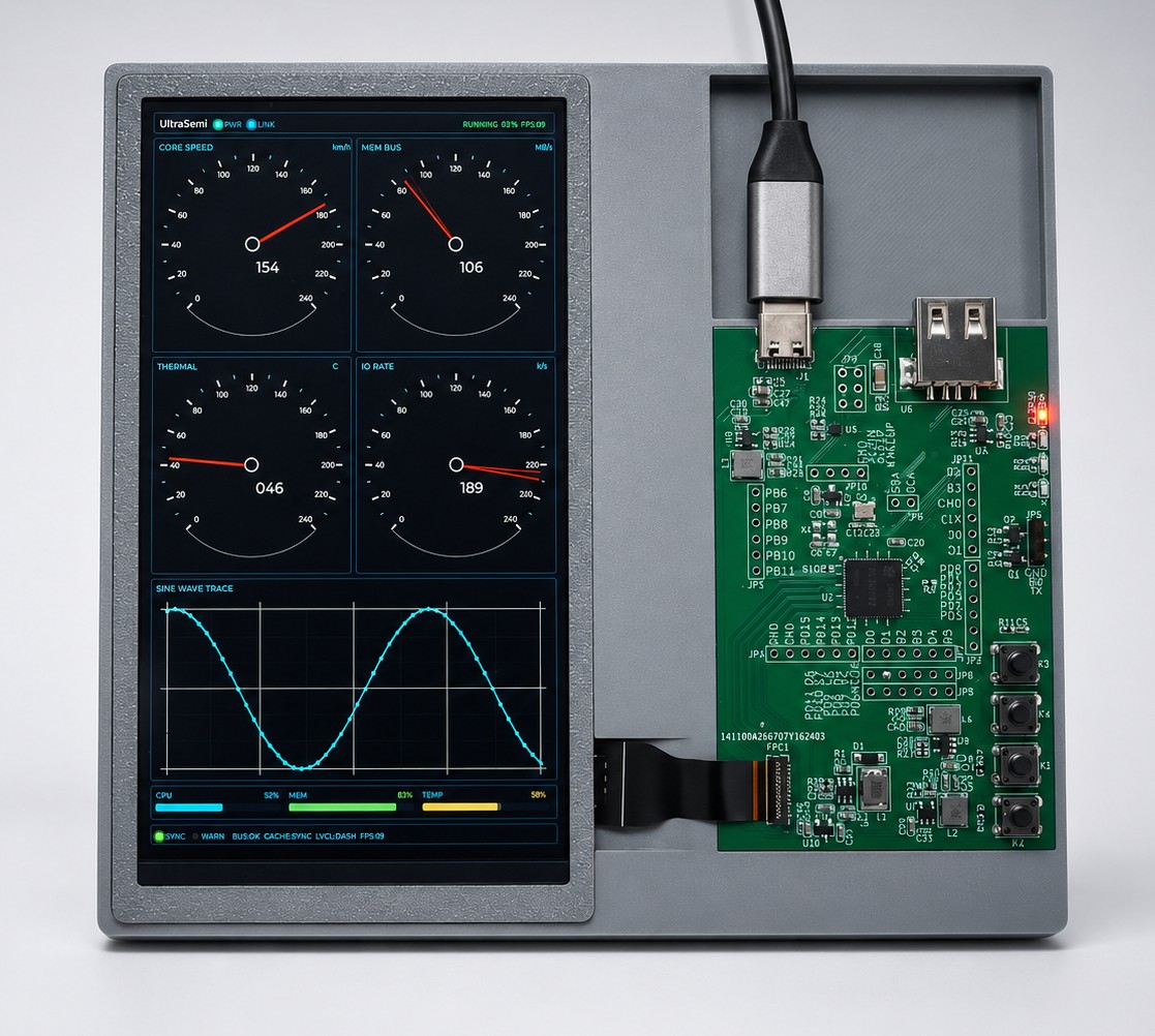
The photo above shows a 720P portrait sample: a 720 × 1280 MIPI panel on the left and the display controller board on the right, linked by an FFC. The host supplies power and content over USB-C. The UI in this sample is a system monitor dashboard; the same hardware can host badge-style artwork, GIF slideshows, or lyric pages.
1. Positioning
The target form factor is clear:
- Panel resolution:
720 × 1280(portrait) - Panel interface:
MIPI-DSI - Host side: a PC expands a secondary or information display over USB
- Product feel: a badge-size mini screen—desktop stand, chassis side, or clip mount—for dynamic visuals and status
Unlike a conventional external monitor, this category prioritizes:
| Dimension | Requirement |
|---|---|
| Size & industrial design | Mini screen, thin body—close to a can badge / pin / mini frame |
| Link simplicity | Prefer direct MIPI drive; fewer bridge ICs and cables |
| Power & thermals | USB-powered, suitable for always-on use |
| UI smoothness | 720P@60fps-class UI and image slideshows feel fluid |
| Content | Stills, GIFs, lyrics, notifications, simple controls—not heavy 3D |
2. System Architecture
A typical link looks like this:
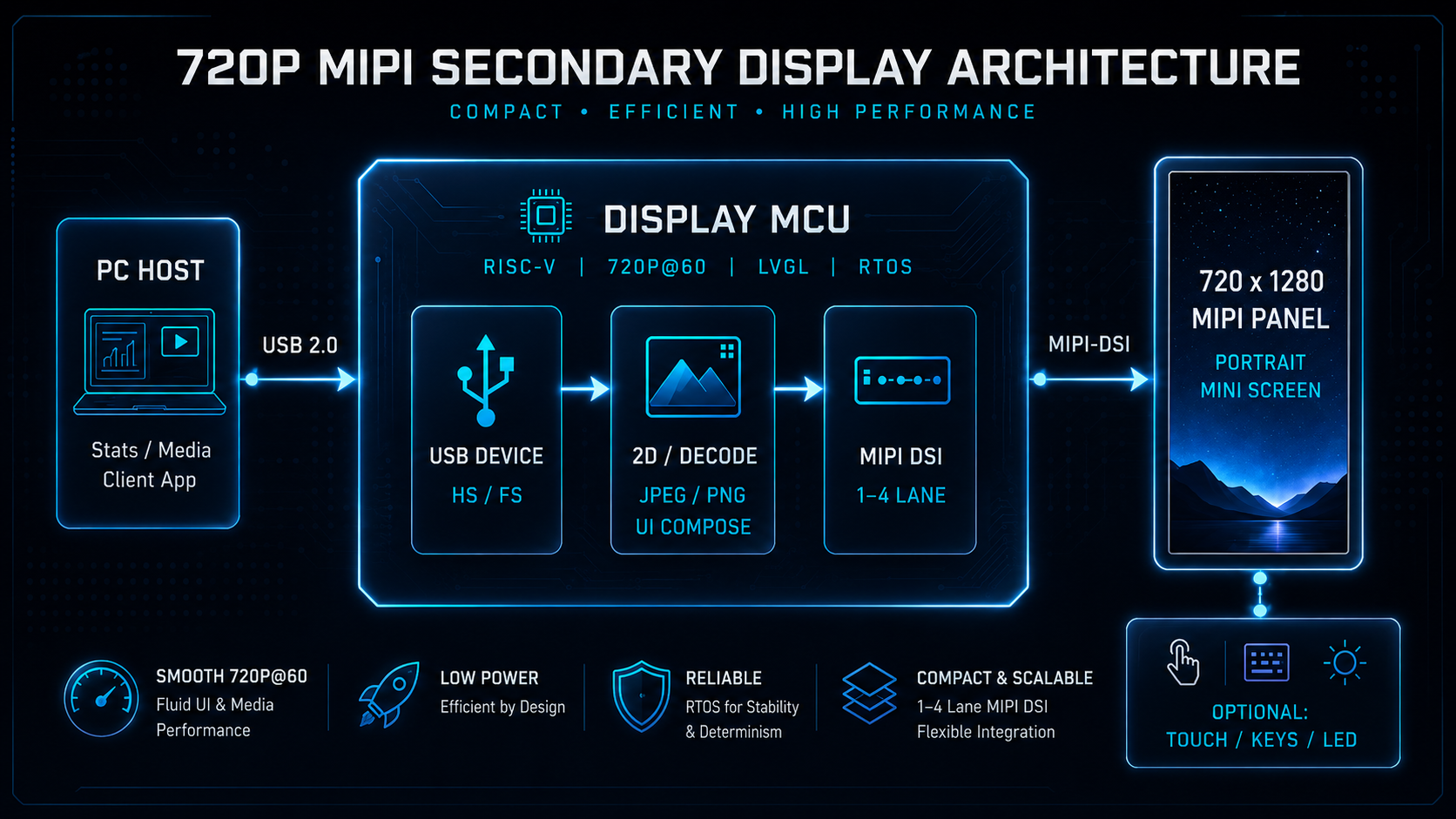
PC / Host
   │  USB 2.0
   ▼
Display MCU (RISC-V industrial display MCU)
   │  MIPI-DSI (1–4 lanes)
   ▼
720 × 1280 MIPI panel
   │
   └─ Optional: touch (I²C), keys, RGB LED, in-shell sensors
Size the MCU for reliable single-screen 720P, not 4K headroom. Practical capability targets:
- Single display:
720P @ 60fpsUI / graphics refresh - Display I/O: native
MIPI-DSI, with RGB / I8080 / SPI / QSPI compatibility for early panel swaps - Graphics & media: 2D accelerate (rotate / scale / blend), JPEG encode/decode, PNG decode—well matched to badge-screen artwork and animation
- Host link:
USB 2.0(HS/FS) for enumeration, firmware update, and command / media delivery - Software: RTOS or bare-metal, with LVGL-class lightweight GUIs, or a dedicated info-terminal firmware
You do not need a full OS-level “extended desktop” protocol on day one. Production stacks usually land in tiers:
- Info secondary: host sends text, image URLs, or status fields over USB custom / CDC / HID; device renders locally.
- Media secondary: host pushes JPEG / PNG / animation frames; device decodes and updates the panel.
- System secondary: add virtual-display class protocols (higher bandwidth, driver, and OS compatibility cost).
For badge-style mini screens, the first two tiers usually deliver a stable experience at a controllable cost.
3. Why 720×1280 MIPI
3.1 Size and content fit
720 × 1280 matches common phone portrait ratios. As a badge / desktop mini screen:
- Text remains readable for notifications, lyrics, todos, quotes, and sensor values
- Imagery looks solid for portraits, album art, stickers, and looping GIFs
- Enclosure tooling can follow a rounded “badge screen” language shared with acrylic can badges and collectible merch
3.2 MIPI vs SPI for this resolution
SPI / QSPI panels fit lower resolutions or mostly static UI. At full-color 720P with higher refresh, bandwidth pressure rises quickly. MIPI-DSI is a better fit for:
- Higher resolution and refresh
- Shorter board routes and fewer data pins
- Broad module availability from phone / industrial portrait stock
When bringing a panel up, lock lane count, Video / Command mode, RGB888/666/565, init sequences, reset / backlight levels, and TE / reset timing from the panel datasheet.
3.3 Realistic USB bandwidth for secondary displays
USB 2.0 cannot sustain continuous uncompressed full-frame RGB. Prefer:
- Dirty-rectangle / region updates
- JPEG or compressed texture delivery + local decode
- Local themes and cached assets, with the host sending commands only
That keeps the “always-on secondary” feel without saturating USB or MCU DRAM.
4. Panel Bring-Up Checklist
4.1 MIPI-DSI configuration
Fix one target panel early and freeze:
| Item | Verify |
|---|---|
| Resolution / orientation | 720×1280; whether 90°/270° rotation is required |
| Lanes | 2-lane or 4-lane (confirm with datasheet and SI) |
| Mode | Video or Command; Burst / Non-burst |
| Pixel format | Prefer RGB888; drop to RGB565 if bandwidth is tight |
| Init | Power-on order, reset pulse, Sleep Out, display-on sequence |
| Backlight | PWM range, low-brightness flicker, USB power margin |
Portrait products are often mounted upright physically; software then decides rotation. Hardware rotate in the display / 2D engine reduces CPU copies.
4.2 UI and motion content
Peak content for badge and desktop mini screens is usually:
- Static artwork plus local animation
- GIF / frame PNG sequences
- Scrolling lyrics, danmaku, notification cards
- Simple touch menus (brightness, theme, page flip)
A MCU with 720P-class 2D and JPEG/PNG hardware decode keeps UI smoother and fits all-day USB-powered duty. LVGL-class frameworks cover most badge-screen interaction; full desktop mirroring is out of scope for this BOM class.
4.3 Multi-panel extension (optional)
If the line grows from one 720P badge screen to “main panel + small status disks,” reuse the same display-MCU family: MIPI for 720P, SPI/QSPI for smaller indicators. Stabilize single-lane 720P first, then budget multi-panel memory and bandwidth.
5. Product Form Suggestions
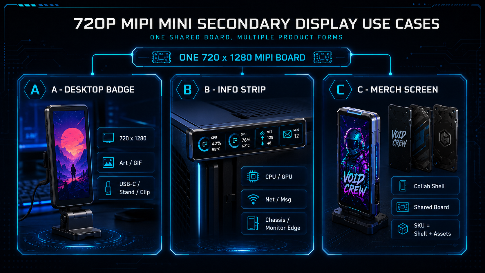
Form A: Desktop badge secondary
- Shell styled like a can badge / desk stand
- Default: album, GIF, schedule
- One key or touch for page flips
- USB-C for power and data
Form B: Chassis / desk info strip
- Narrow-bezel portrait panel on a side panel or monitor edge
- Shows CPU / GPU load, network rate, message summary
- Lightweight host client pushes fields
Form C: Merch / collab mini screen
- SKU differences mostly in shell, cover glass, and factory asset packs
- Shared firmware; assets via OTA or host import
- Sell the “small screen that moves”—looping portraits, audio bars, event countdowns
All three can share one 720×1280 MIPI board and diverge only in mechanics and assets—helpful for tooling and certification cost.
6. Selection and Production Checklist
- Panel: resolution, viewing angle, brightness, touch option, long-term supply and alternates
- MCU: MIPI-DSI lane / frame-rate coverage; USB, Flash, DDR/SRAM for UI + decode buffers
- Power: 5V USB input, backlight peaks, hot-plug surge, ESD
- EMC: MIPI differential routing, ground reference, chassis ground, USB common-mode filtering
- Firmware: splash, recovery from bad panels, watchdog, fail-safe update
- UX: minimum brightness, touch feel, portrait/landscape content fit, reconnect after host sleep
Confirm electricals, packages, and registers against the chosen MCU/panel datasheets and sample-board measurements.
7. Summary
A 720 × 1280 MIPI panel drive path fits PC secondary displays and badge-style mini screens: compact size, portrait-friendly content, mature interfaces. Three engineering anchors get a sample moving quickly—
- Direct MIPI 720P—stabilize init and refresh
- USB for commands and compressed media—compose / decode on-device
- Differentiate badge / info strip / collab shells—reuse one mainboard
When evaluating a similar mini secondary or badge-screen BOM, converge from both ends: the target panel datasheet and the intended content model (local slideshow vs system-level secondary), then lock MCU peripherals and firmware scope.